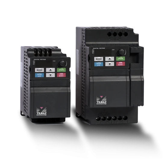
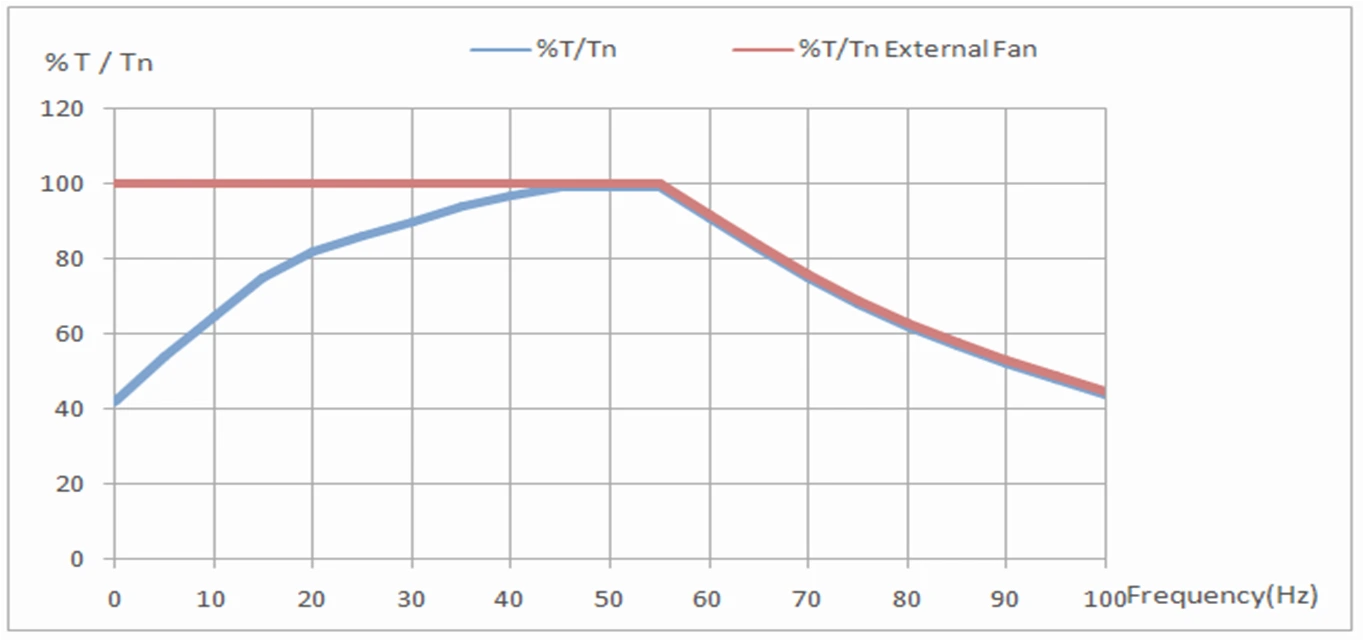
Generally, three-phase motors can be run safely using a mono-phase input drives at small powers. Single-phase drives have three-phase output as standard and are suitable for three-phase motor operation. There is also the case of connecting the two phases we have (in case of monophase supply) to the two phases of the motor and connecting the third phase with a capacitor (to create a 90 degree phase difference). The name of this connection type is referred to as the Steinmetz connection in the literature. However, such use is not recommended because it results inconsiderable motor performance loss. If the motor is to be operated at the full power rating indicated on the nameplate, damage to the motor can be expected.
Basically, we witness that the motors fail and burn out due to overloading and the resulting overcurrent and overheating. At this point, motor protection against excessive heat can be classified under two different concepts.Direct Protection;Equipment such as PTC, Thermostat, PT100 etc. which are also in our options for motors, are placed directly inside the windings and inform outside world for the real winding temperature (or temperature threshold exceeded) of the motor and serve to stop the motor before it is damaged.This is not solely managed by having the proper accessory in the motor but also must be a result of the precautions to be taken by the application/field engineer in the operation scenario of motor. Since the measurement and indication is directly dependent on temperature, we can call it a direct protection method.Indirect Protection;Another commonly preferred method is to protect the motor by monitoring motor current and relying on the 'motor overheated' logic as; “if the overloading motor current has been drawn for a prolonged time, motor must be overheated.” For this, various electrical switchgear equipment (thermal relays, motor protection switches, etc.) are available.Although they target the same goal, these two methods cannot be considered as exact-equivalent due to the difference in working principles.
In terms of body and/or package size, they are the motors that fit in a smaller frame size than as indicated in IEC norms for the same power and pole number. From time to time, they are preferred due to the need of fitting in a confined space, cost issues or weight considerations.
We call the service factor as the ratio of the maximum power it can continuously deliver before damage occurs, to the power written on the nameplate. The service factor is a measure of capacity to continue operation without damage in case of real field level operation odds such as extra loading or above normal environmental temperature.ELK Motors generally have service factors such as 1.15 .. 1.20 for IE2 efficiency class and 1.20 .. 1.25 for IE3 class motors.
in a nutshell;
Power: Indicates the power of the motor in kW. Expressions as HP (horsepower) are also available. This is the mechanical output power.
RPM: expression of the rated speed of the motor at rated load in rpm (or RPM).
Supply voltage and frequency: These are the values of the rated supply voltage (Volts) and frequency (Hz). In addition, the voltage values to be given in case of delta (Delta - D) and star (Star - Y) connection in three-phase motors are also written.
Type of motor according to supply: Asynchronous motors are mostly produced as single-phase (single-phase) or three-phase (three-phase) versions. Motors supplied from a single phase supply (i.e. phase, neutral) are called single-phase and motors fed from a three phase supply (i.e. R-S-T or L1-L2-L3) are called three-phase, as the hint is in the name.
Rated current: It is the current (A) value that the motor will draw from mains under normal conditions while operating at full load as also indicated in the nameplate. Loads above this current value are generally classified as overloading, and motors operating in this way for a long time may be damaged.
Declarations and certificates: There may be certificates/stamps such as CE declaration indicating that it is produced in accordance with European machinery directives, UL, cSA, which indicates compliance with American and Canadian countries, and ECA, which indicates compliance with Russia. Many declarations/certifications can be available for different regions of the world.
Motor Mounting Structure:There are standard mounting types available for asynchronous motors. Such as; B3: Foot mount, B5 / B14 flange mount or combinations like B35: foot + flange…
Running regime: Generally, the power and performance values on the labels are given according to the continuous operation of the motors, which in this case we call S1 – continuous duty. However, there are many other operation duty types are also defined from S2 .. S9. So, for example, S3-%40ED means; the motor will run at full load for the %40 of the time and remaining %60 of the time it will be stopped. If this is the case, it can be calculated that the motor can delivery higher power output compared to S1 duty data due to the allowance of resting time. These duty types can be classified as intermittent duty in general.
Serial Number: It is a useful registration information, especially to query a motor from the factory database in the future.
Insulation class: ELK Motors have F class insulation as standard. This means that the motor windings are suitable for heating up to 155 degrees Celcius. Optionally class H can be manufactured which means 180 degrees Celcius.
Weight: It is the net weight of the motor. This weight does not include the packaging weight.
Efficiency class: As ELK Motor; We manufacture motors with efficiency class IE2, IE3 and IE4. And special design / branch specific motors which do not fall within IE concept.
IP protection class: As ELK Motor, our standard is IP55 protected motors. IP stands for Ingress Protection and defines the tightness of the motor against water and dust ingress from environment to inside of the motor.
Bearing types:Information on the used bearings in the motor. Application engineer must ensure that the actual loading (both in radial and axial axis) should not exceed the bearings limit values. If this is the case, optionally available reinforced bearings can be used.
Origin: Indicates the country where the product was produced. ELK Motors does not use contract manufacturing other than its own factories. We produce according to the European regulations &design criteria with 100% in-house and national R&D team. ELK motor is already a government approved R&D center.
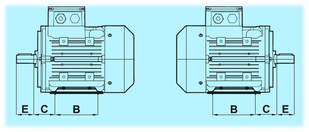
63-180 frame size Elk Motors provides flexibility for different mounting types through their detachable feet which can be mounted on three sides. This feature allows terminal box assembly on the desired sides. Terminal box is on the top for standards motors. 200-315 frame size motors have fixed feet contruction. However, additional R&D studies are already in operation to get full range with detachable feet. Please consult sales for updated info.

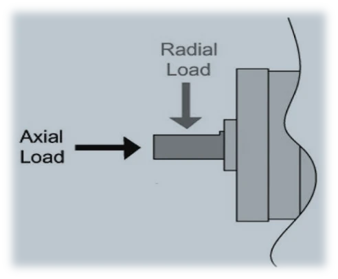
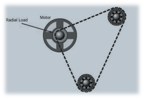
Unless otherwise stated, ball bearings are used as standard in our motors. Two bearing forces, axial and radial, are defined for each bearing. Axial force; it is the axis force that presses the motor shaft inward or tries to pull the shaft outward. Radial force is the force that presses the motor shaft from the side. Generally, in applications where belt-pulley is used as a transmission between the motor and the load, if the tension of the belt to transfer the movement produces a radial load that is more than the standard bearings can handle, the front bearings of the motor can be selected as cylindrical and reinforced bearing class, also called NU type, upon request. Apart from this, structures with grease fittings that allow re-lubricating for the bearings, especially in bigger power motors, can also be provided.
Our Motors are subject to 3 different tests1. After the windings are placed on the stator (All motors):a.Surge testb. Resistance measurementsc. Insulation measurementsd. Partial discharge and high voltage tests
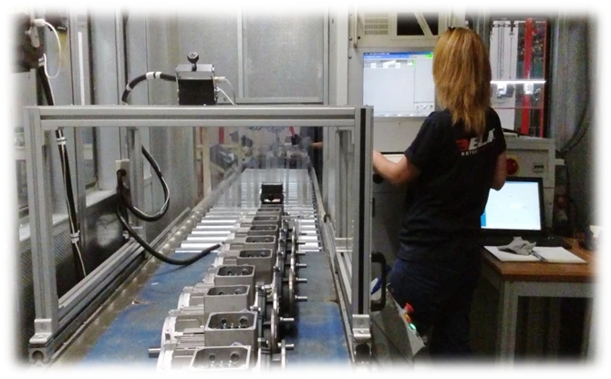
2. During assembly (All motors)a.Low voltage start testb.Idle test at rated voltagec. Sound level measurements
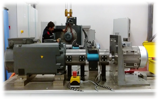
3.Performance and warm-up tests under full load in the laboratory. (Sampling method)
It is feedback equipment that reports the speed of the motor and, in some very specific applications, its position to the main controller (usually a variable speed drive). It is mostly demanded wheremotor is to be used with a drive and in applications that require closed loop vector control which provides full torque down to zero speed.
In large powerful motors and driver-running operation, an undesirable current called 'bearing current' may circulate over the bearings and this reduces the life of the bearing. One method to get rid of this phenomenon is to take the motor bearing as an isolated bearing.
If the humidity of the air turns into water by condensation (dew formation) due to atmospheric conditions and the weather conditions in the area where the motor will operate, then moisture-induced water may have accumulated inside the motor, also on the windings. Especially if it is a motor that driven by a variable speed drive, this situation has the potential to create even more problems in such systems, since the power outputs of a typical commercially available drive has so called PWM high frequency very fast rising voltage form. As a countermeasure against dew,we can have heater inside the motor upon request. These heaters are run before the motor is started to remove the condensed water – especially accumulated on windings.
The abbreviation IP stands forIngress Protetion and means protection against solid/liquid penetration. After the abbreviation IP, we see two numbers. Of these, the ones in the tens digit means protection against solid and the one in the ones digit means protection against liquid. ELK Motors are produced in IP55 protection class as standard. IP56, IP65 and IP66 levels are also possible on request.
IP5x : Partial protection against dust. Under normal conditions, dust may enter the motor, but this is not expected to cause problems in terms of operation.
IP6x : Fully enclosed, dustproof design with dust protection.
IPx4 : Protected against spray from all directions, splash water.
IPx5 : Protected against low pressure water coming from all directions. For example, running water from the faucet.
IPx6 : Protected against high pressure water coming from all directions.
#BBD0E0 »
- Operating voltage and frequency (1 phase, 3 phase / 220V, 380V, 400V, 440V, 460V / 50 Hz, 60 Hz)
- Speed of Motor.
- Mounting Structure: Such as Footed B3, Flange B5, Footed Flange B3 B5
- The magnitude of the axial load.
- The magnitude of radial load.
- The temperature of the environment in which it will be operated.
- The altitude of the environment in which it will be operated.
- Protection type: such as IP54, IP55.
- Number of starts per hour: Start/h
- Operating type (Running Mode): S1, S3, S5 etc.
- Service Factor such as 1.0, 1.10, 1.15 – 1.20 – 1.25 etc
- Humidity degree of the environment where it will be operated: Whether a heater and drainage is desired.
- Whether or not thermistor PTC thermistor will be required for system safety.
The most important condition for producing a long-lasting, low-cost, competitive machine that meets customer expectations is the correct selection of the electric motor. The most important factors in choosing the right electric motor are the characteristics of the job and the environment in which the machine will operate. Giving the same type of motor to every customer or similar application may not always give the right result. It is to find out what the system needs in an optimum way. In this sense, after-sales and technical support services are of great importance.
Ambient temperature, humidity in the environment, presence of flammable and explosive gas in the environment are the most important parameters that determine the environment whether the machine will be exposed to dust, water and tropical conditions.
Features such as how many hours the machine will work per day, intermittent or continuous operation status, sensitivity of movement, characteristics of the energy source, expected efficiency from the system, response time of the system to commands are the parameters that determine the characteristics of the work. Depending on these features, the insulation class, protection class, type, power and speed of the electric motor should be determined. Otherwise, the system will either be very expensive and inefficient, or it will fail in a short time, causing customer dissatisfaction.
Bearing is one of the most important elements of the motor, which consists of two inner and outer rings and parts such as balls and rollers rolling between them, making rotational motion with the least possible friction.The structure of the bearing includes the inner ring, outer ring, rolling elements and cage. Bearings are produced to withstand very strong mechanical effects.
The mechanical movement in the motor must be transmitted with the least amount of friction.The increase in friction directly affects the efficiency of the motor.
There are some cases where the bearing is damaged, and the motor is adversely affected. A failure that may occur in the bearing reduces the efficiency of the motor. It should be correctly diagnosed whether there is a fault in the bearings, which is an element that directly affects the operation of the motor.
Every bearing has a lifespan. However, according to a study, it has been revealed that only 34% of the bearings in electric motors have completed their own life. Others, on the other hand, must be replaced earlier due to a malfunction before completing their own life. Bearings are manufactured as long-lasting, durable, high-powered. However, failures may occur in bearings due to lack of maintenance, lack of precautions and misuse or incorrect assembly.
Bearings become mechanically fatigued for various reasons. Symptoms of this may be in the form of particles breaking off from the bearing surface. Shear stresses occur when the rolling elements in the bearing contact the load-bearing surface. These stresses create cracks at certain points of the surface. When rolling elements such as balls pass over these cracks during the rotational motion, the particles break off. An important point here is the number of revolutions that the bearing can withstand and the operating time the bearing will operate. The fatigue indication of the bearing depends on the ambient conditions, the load and the mechanical strength of the parts that make up the bearing.
The approximate life of an electric motor with the right power and structure can be estimated like 15 years. Under normal conditions, it is desirable for the motor to run smoothly for this period. However, sometimes the motor may burn out due to external factors, sometimes not taking adequate protection measures, and sometimes due to problems arising from the motor. The first thing that comes to our mind is to rewind the motor. However, every time the motor is rewound, its life is shorter than the previous one and the current it draws may get higher.
Rewinding the motor; since it is highly likely to causes a decrease in motor efficiency either, and also considering the cost of manual windinglabor, material cost and time loss; as a general rule of thumb, we recommend replacing up to frame size 100 and smaller motors rather than repairing them.
In addition;
• We recommend not to increase the temperature of the sheet package above 200 °C during removal of the burnt wrap. Otherwise, the sheet loses its electrical properties and changes in shape geometrically.
13.5EM of the IEC 60034-1 standard regarding Electromagnetic compatibility (EMC);
Cage induction machines do not need to be measured.
It is not intended for a test to be suitable for motors including standard.
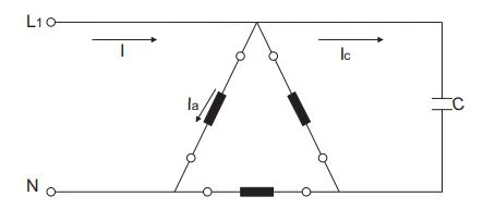
If three-phase Δ/ connected asynchronous motors ( induction motors ) are required to be operated in single-phase systems, a capacitor is connected in parallel with a phase group coils in both connections. Capacitor enables its development and operation in a single phase circuit. Since there is a phase difference between the current passing through the motor windings (Ia) and the current passing through the capacitor (Ic), torque is generated. In other words, it creates a rotating field due to the phase difference between the currents passing with the help of a single phase and capacitor in the stator windings. In this method, when a three-phase asynchronous motor ( induction motor ) operates in a single-phase system, the motor power decreases by 40%-45% compared to the three-phase supply. To increase the starting torque, the second capacitor is used during starting. Electrolytic capacitors that will stay in circuit for a short time are preferred.
- Connection diagram of a three-phase asynchronous motor ( induction motor ) with a capacitor in a single-phase circuit
Operation of star connected asynchronous motor ( induction motor ) with capacitors in single phase System
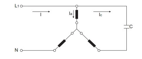
Running of a delta-connected asynchronous motor ( induction motor ) with a capacitor in a single-phase System.
You can contact us directly .Your request will be answered as soon as possible.
To summarize this briefly with the main headings:
- Original design and production. Uses 100% own engineering and design.
- Innovative design. Since the day it was founded, it has designed the motor according to IE3 motors, even before the world's more globally known companies.
- Design that allows flexible use: Feet can be disassembled, and the terminal box rotated by 90 degrees, pre-exchangeable due to being front-complete, feet made of steel sheet and more durable.
- Achieving IE2 and even IE3 efficiency levels in compact motors.
- High service factor. In other words, it has more tolerance and durability against unexpected adverse events that may occur in practice (increase in ambient temperature, increase in load, difficulty in running regime, etc.)
- High starting torque
- High efficiency value. ELK Motors have higher efficiency values than the minimum efficiency values forced by the standards as the minimum efficiency value and considered sufficient for classification.
Asynchronous motors (induction motors) are machines that convert the alternating current applied to the stator windings into mechanical energy in the rotor. These motors are also called induction motors because they work according to the induction principle. In this context, they are the most widely used equipment for manufacturing in the whole industry and for converting electrical energy into motion in machines.
The most important feature that distinguishes asynchronous motors (induction motors ) from synchronous motors: While the speed of the electrical field (synchronous speed) formed in the motor is a clear and constant number in terms of the supply frequency and the number of poles of the motor, the actual rotational speed of the shaft in asynchronous motors (induction motors ) is less than this synchronous speed and the number of revolutions depends on the load. That is, the number of revolutions is not constant and varies up to about 2%, depending on the load, depending on the power and design of the motor. This difference is called 'slip' in the literature.
- They do not require constant care. Asynchronous motor ( induction motor ) operating in a suitable environment needs bearing replacement after about 10 years.
- Spare parts are easily accessible.
- It is cheaper than another type of motor of the same power.
- They are more robust than other motor types.
- They do not produce arcs (sparks) during operation.
- The rpm doesn't change much during load changes.
- The number of rpm can be easily adjusted with the help of electronic circuits (frequency converters).
- They are manufactured from small power to very large power.
- Can be produced as single and three phase.
- As in synchronous machines, there is no need for a second supply source (like in DC motors).
- There are no magnets inside which are susceptible for demagnetising in the future.
Due to the reasons mentioned above, Asynchronous electric motors are the most used electric motors in practice. Asynchronous Electric motors are produced in protection classes such as IP54 IP55 IP56 and IP66 and in construction forms such as B3 B5 B14 B34 B35 and they have the advantage of working in any type of assembly.
- They draw 4-8 times more current than their nominal current during starting.
- The number of rpm change is possible by only changing the supply frequency.
One of the reasons for the widespread use of asynchronous motors ( induction motors ) is that alternating current is easy to obtain and transmit. 90% of the motors used in the industry are asynchronous motors ( induction motors ) due to the low risk of failure due to the lack of many mechanical parts in the structure of the asynchronous motor ( induction motor ) and the easy maintenance due to its simple structure.Low voltage three-phase asynchronous electric motor can be produced from 0.12 kW to 3500 kW and is widely available in the market. It is very widely used in mills,pumps, compressors, fans, conveyors, presses, machining centers and hydraulic units.
Standard ELK Motors that have been manufactured for 50 Hz power supply can be used at 60 Hz network. The ratios given below indicate changes in the given rated values.
50 Hz Rated Voltage | 60 Hz Rated Voltage | Rated Speed | Rated Power | Rated Torque | Rated Current | Starting Torque | Break Down Torque | Starting Current |
| 230V | 220V | 1.193 | 1 | 0.84 | 0.97 | 0.77 | 0.8 | 0.8 |
| 400V | 380V | 1.193 | 1 | 0.84 | 0.97 | 0.77 | 0.8 | 0.8 |
| 400V | 440V | 1.20 | 1.16 | 0.97 | 0.98 | 0.87 | 0.9 | 0.9 |
Smooth operation is guaranteed by providing both the service factor, F/B or H/B margin insulation/heating class and optional features (e.g. thermisor, forced fan, encoder, insulated bearing and even special winding motor wrapped according to different voltage/frequency, etc.) from time to time in driver applications.
